
LEDs and laser diodes can be supplied with voltage in two ways:
- Battery box:
The battery box module contains two AA batteries and can be switched on and off using a switch. The switch uses an integrated LED to indicate whether the battery box is switched on. The battery box can be soldered together yourself as part of the modular design presented here. - USB:
USB connections (with switch) can also be soldered to the LED and laser diode. Both can then be supplied with simple USB power supply units or power banks. This has the disadvantage that no button (see BB84) can be integrated. When using power banks, it should also be noted that laser diodes and LEDs generally “consume” little power (convert energy) and the power banks therefore often switch themselves off after a few seconds.
Battery box
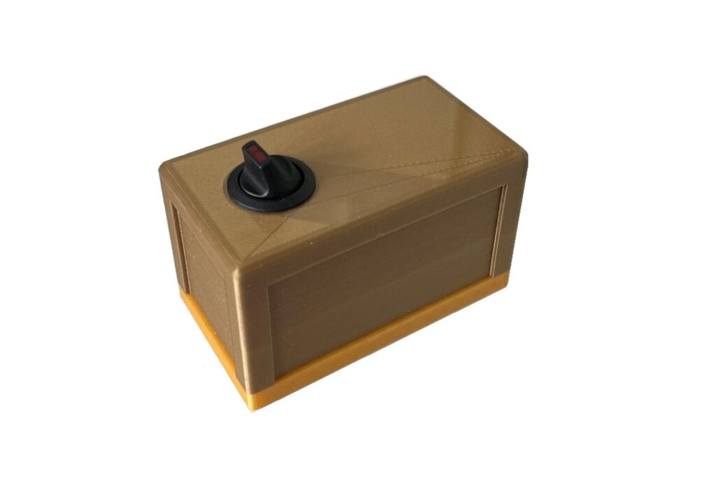
The battery box serves as a voltage source for the laser diode and the LED. The battery box switch is equipped with an LED so that it is possible to detect whether the battery box is switched on or off even when the light source is not plugged in.
On this page you will find information about the assembly, the special features and the possible experiments.
Assembly
Material:
- 01D_Go_V*_battery_box_base
- 02D_Br_V*_battery_box_cover
- 1x DC-Socket
- 1x Round toggle switch
- 1x Battery holder AA
- 1x Resistor 47 Ohm
- 2x Battery AA
- 4x Allen cylinder head screw, M3x12
- 2x Zip tie(mind. 15 cm long and max. 4 mm wide)
- Twin stranded wire (1 pc., ca. 9cm; 1 pc., ca. 12 cm)
- Heat-shrink tubing
- Soldering tin
Tools:
- Allen key – 2,5 mm
- Soldering iron (+tip for threaded inserts)
- “Board holder” for soldering
- Side cutter
- Stripping tool
- Lighter
- (Pipe) pliers
- (ratchet + socket wrench attachment 12 mm)
- (tweezers)
Circuit Diagram
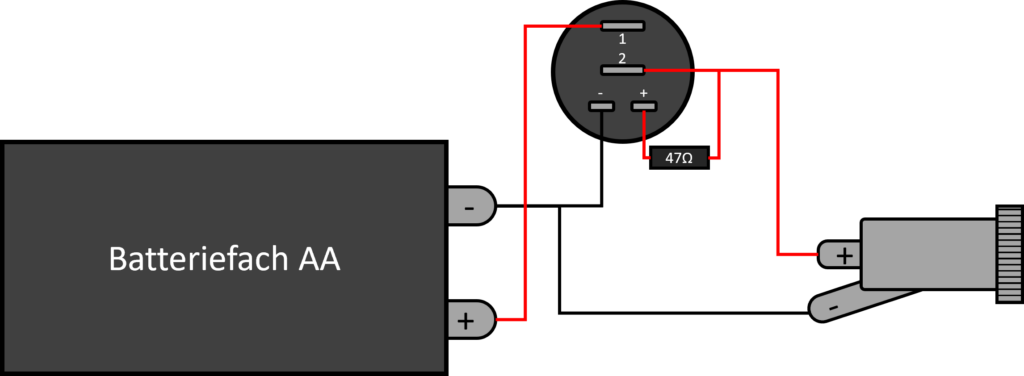
This circuit diagram shows the circuit with an AA battery compartment, a changeover switch and a hollow socket, with an additional 47 Ω resistor at the changeover switch.
- The positive pole of the battery compartment is connected to the upper contact of the changeover switch.
- The negative pole of the battery compartment is connected to the negative pole of the changeover unit and the negative pole of the hollow socket.
- The positive pole of the hollow socket is connected to the middle contact of the changeover switch and its positive pole, which is preceded by a resistor (47 Ω).
- Battery compartment (left): Supplies the circuit with voltage. The positive pole (red cable) feeds the voltage into the circuit, the negative pole is the common ground.
- Changeover switch (center): A single-pole changeover switch with three contacts. It makes it possible to switch between two connections.
- Resistor (47 Ω): Limits the current or voltage for one of the switch positions.
- Hollow socket (right): Serves as an output for the supply voltage of a connected device.
Video tutorial
You will also find detailed instructions for assembly as well as a component and material list with the STL files for 3D printing and links to the relevant stores.
Special Features
The battery box does not fit on the grid
Although the battery box is also held together with screws, the dimensions are not suitable for holding it firmly on the grid. Especially when setting up sensitive experiments such as interferometers, the battery box should be positioned next to the grid so that the interference behavior is not disturbed by vibrations of the grid.
Experiments
- Michelson interferometer – 1 pc.
- Michelson interferometer with piezo element – 1 pc.
- Mach-Zehnder interferometer – 1 pc.
- Slit & diffraction grating – 1 pc.
- Polarization and Law of Malus – 1 pc.
- BB84 protocol – 1 pc.