
Experiments on the polarisation of light provide a clear introduction to an important aspect of wave optics. Using various light sources and polarisation filters, different polarisation states can be made visible and examined. In the classroom, these experiments can be used in the context of light propagation, reflection, or material properties, for example, to convey the behavior of polarised light and its technical applications in an understandable way.
Polarisation describes the orientation of the plane of oscillation of the electric field vector of a light wave. While natural light is randomly polarised, various optical elements can be used to generate and analyse a specific polarisation. This plays an important role in optics, for example in displays, camera filters or quantum optics. The polarisation of light is of great importance in many areas. In materials science, it is used for stress analysis, in chemistry to determine the concentration of optically active substances, and polarisation filters play a central role in optoelectronics. Polarisation is also essential in quantum optics, for example for experiments on quantum cryptography or quantum erasers.
On this page, you will find all the information about the various experiments and their setup, special features, and working materials for use in the classroom.
Possible experiments are:
- Polarisation of a laser diode
- Polarisation of different light sources
- Polarising properties of beam splitters
- Law of Malus
- Rotation of polarisation with polarising filters (inverse quantum xenon effect)
Polarisation of a Laser Diode
The experiment investigates the polarisation state of light emitted by a laser diode. By observing the transmitted intensity through a rotating polarisation filter, the linear polarisation of the laser beam can be demonstrated clearly.
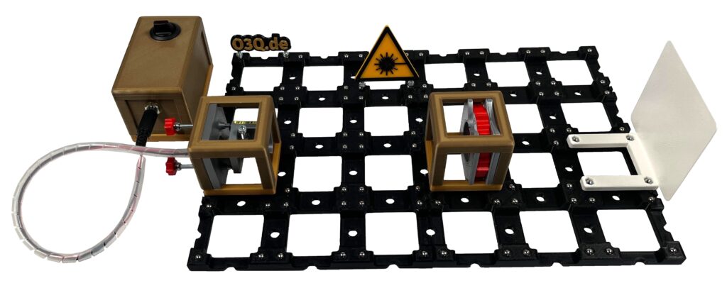
In addition to qualitative observation of the intensity variation on a screen, quantitative measurements can be carried out by replacing the screen with a light sensor. This allows precise determination of the degree of polarisation.
Below you will find all the information you need about the structure and working materials for use in class.
Structure
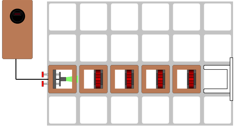
Schematic Structure
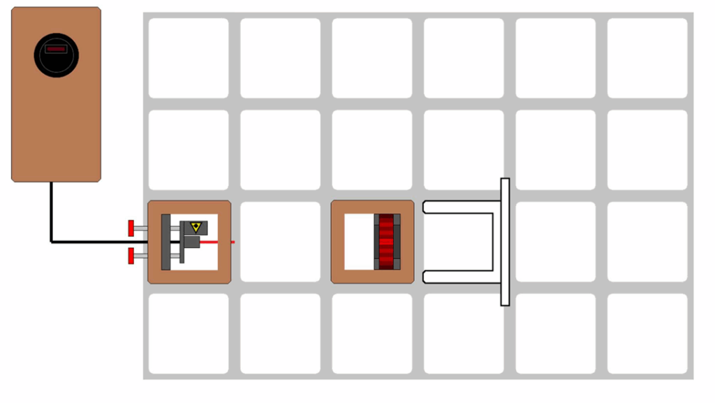
Modules Required:
- Laser diode (USB) or Laser diode
- Battery box
- Polarizing filter
- Screen or Light sensor
- Baseplate (min. 4×4)
Here you will find a complete print and component list.
Working Materials
Coming soon
Polarisation of Different Light Sources
This experiment compares the polarisation properties of various light sources such as laser diodes and LEDs. By analysing the transmitted light through a rotating polarisation filter, differences between polarised and unpolarised light become clearly visible. While laser light typically shows a well-defined linear polarisation, thermal or LED light is usually unpolarised.

By replacing the screen with a light sensor, the transmitted intensity can be measured quantitatively, allowing a detailed comparison of the polarisation behaviour of different sources.
Below you will find all the information you need about the structure and working materials for use in class.
Structure
Schematic Structure

Modules Required:
- Laser diode (USB) or Laser diode
- LED
- Battery box
- Polarizing filter
- Screen or Light sensor
- Baseplate (min. 4×4)
Here you will find a complete print and component list.
Working Materials
Coming soon
Polarising properties of Beam Splitters

Law of Malus

This experiment demonstrates the quantitative relationship between light intensity and the angle between two polarisation filters, known as Malus’ law. When linearly polarised light passes through a second, rotatable polarisation filter, the transmitted intensity decreases according to the cosine-squared dependence I=I0 cos2(θ).

Using a photosensor instead of a screen allows the precise measurement of this intensity variation and the experimental verification of the law. The setup provides a clear illustration of how polarisation filters control light transmission and offers an excellent opportunity to connect theory with experiment.
Below you will find all the information you need about the structure and working materials for use in class.
Structure
Schematic Structure

Modules Required:
Here you will find a complete print and component list.
Working Materials
Coming soon.
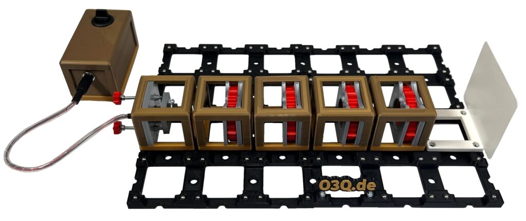
Rotation of Polarisation with Polarising Filters
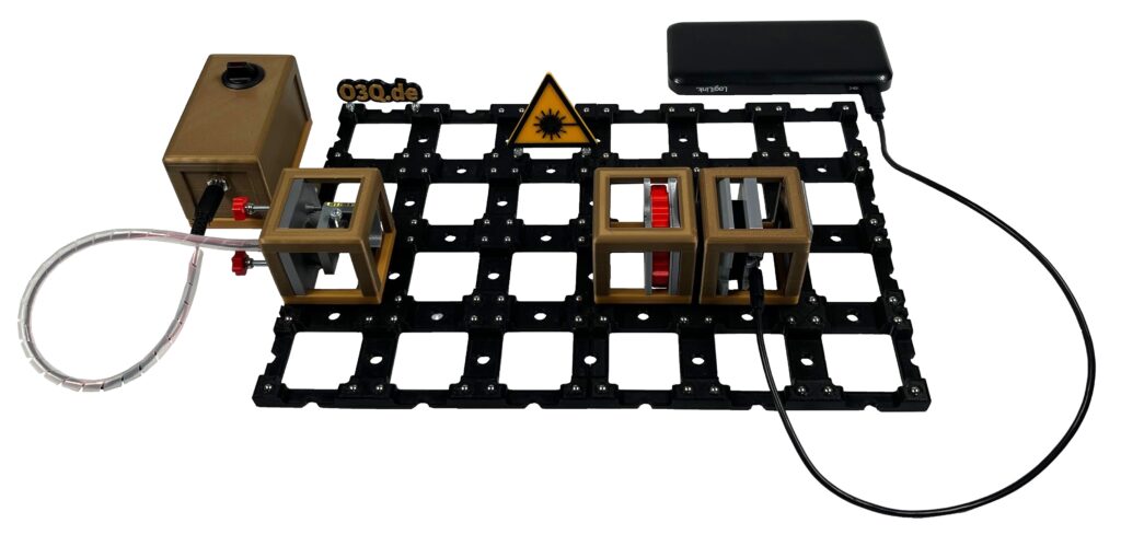
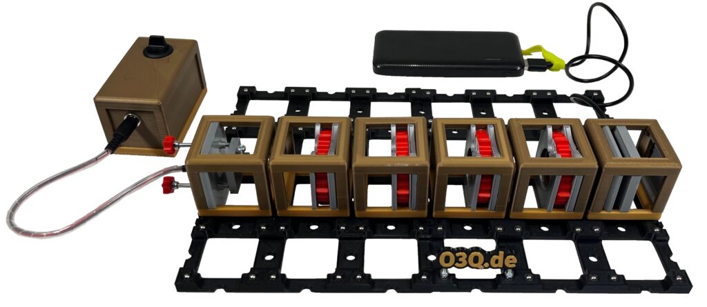
This experiment investigates how the direction of polarisation can be rotated by sequentially passing light through multiple polarisation filters set at different angles. When two polarisation filters are crossed, no light is transmitted; however, inserting a third filter at an intermediate angle allows part of the light to pass through again. This counterintuitive result, sometimes referred to as the inverse quantum xenon effect, demonstrates that the polarisation direction of light can be continuously transformed. The experiment provides an elegant and accessible way to explore the superposition principle and the vector nature of polarised light.
In the qualitative setup, the effect can be clearly observed on a screen by gradually rotating the middle polarisation filter and watching the transmitted light reappear between two crossed filters.
In the quantitative setup, the screen can be replaced by a photosensor to measure the transmitted intensity as a function of the rotation angle of the intermediate filter. This allows for precise analysis of the dependence of light transmission on the relative orientation of the polarisation filters and provides a deeper understanding of the continuous rotation of polarisation.
Below you will find all the information you need about the structure, the special features and working materials for use in class.
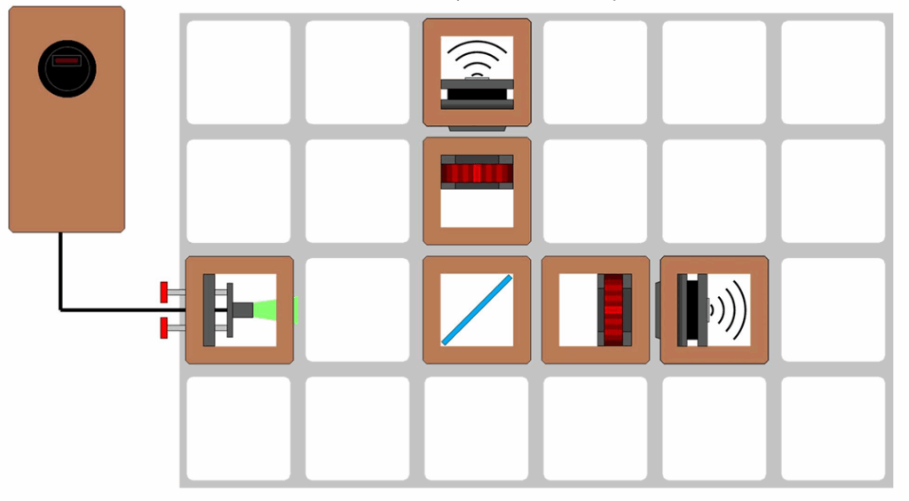
Structure
Schematic structure

NECESSARY MODULES:
- LED
- Battery box
- 4x Polarizing filter
- Screen
- Possibly light sensor
- Baseplate
Here you will find a complete print and component list.
Special Features
Coming soon
Working Materials
Coming soon