
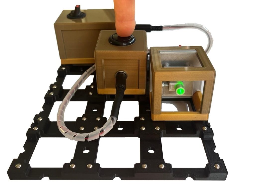
The button is used in the BB84 model experiment to switch the LED on and off quickly and easily.
On this page you will find information about the assembly, the special features and the possible experiments.
Assembly
Material:
- 1x 01B_Go_V*_cube_base 1x1_closed
- 1x 02B_V*_cube_cover 1x1_button
- 1x Barrel connector
- 1x DC-Socket
- 1x Push-button
- 4x Allen cylinder head screw, M3x12
- Heat-shrink tubing
- Twin stranded wire
- Soldering tin
Tools:
- Allen key – 2.5 mm
- Soldering iron (+ tip for threaded inserts)
- “Board holder” for soldering
- Side cutter
- Stripping tool
- lighter
- (Pipe) pliers
Circuit Diagram

The circuit diagram shows the electrical connection between a barrel connector, a push-button and a DC-socket. The barrel connector is shown on the left, which is connected to the positive pole of the push-button via one connection and to the positive pole of the DC-socket via the other connection. The negative pole of the DC-socket is connected to the negative pole of the push-button. The barrel connector serves as the connection for the battery box and the DC-socket as the connection for the LED module.
You will also find detailed instructions for assembly as well as a component and material list with the STL files for 3D printing and links to the relevant stores.
Special features
TENSION
When inserting the cable into the cube cover, it should be knotted before being pulled through. This prevents the connections from breaking.
Experimentes
- BB84 protocol – 1 pc.