
Mirrors are an important component of most optical assemblies. Mirrors are used here that are coated with a reflective layer on the front. This prevents unwanted reflections on the front and back of the glass plate.
There are two variants of mirror suspension in the set, as well as the combination with a piezo element:
- The suspension at a 90° angle is used for
- The suspension at a 45° angle is used for
- The combination of suspension at a 90° angle with a piezo element can be used for
- investigation of the effects of the smallest changes in distance in the arms of the Michelson interferometer on the interference pattern.
90° mirror
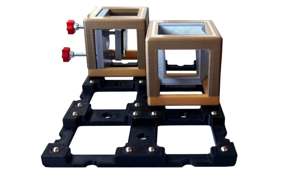
Below you will find information on assembly and possible experiments.
Assembly
The adjustment works in the same way as for the laser diode, the LED and the piezo mirror module.
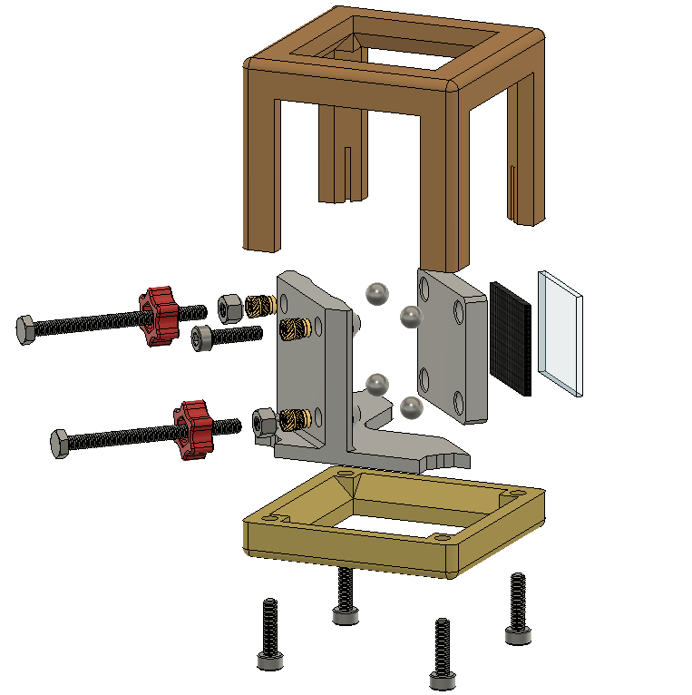
Exploded View

Material:
- 1x 01A_Go_V*_cube_base 1×1
- 1x 02A_Br_V*_cube_cover 1×1
- 1x 10A_Si_V*_insert 90°
- 1x 11C_Si_V*_mirror_plate
- 2x 03A_Re_V*_adjusting_screw_head
- 1x Adhesive pad (20 x 20 mm)
- 1x Front surface mirror (22 x 22 mm)
- 4x Magnetic sphere, ø=5 mm
- 3x Thread insert, M3
- 5x Allen cylinder head screw, M3x12
- 2x Nut, self-locking, M3
- 2x Hexagon head screw, M3x40
Tools:
- Allen key – 2,5 mm
- Soldering iron (+ tip for threaded inserts)
- (Pipe-)wrench
- (ratchet + socket wrench attachment 12 mm)
- (tweezers)
You will also find detailed instructions for assembly, as well as a component and material list with the STL files for 3D printing and links to the relevant stores.
Experiments
- Michelson interferometer – 2 pcs.
- Michelson interferometer with piezo element – 1 pc.
To carry out measurements with the Michelson interferometer, one of the mirrors can be replaced by a mirror piezo module.
Piezo mirror
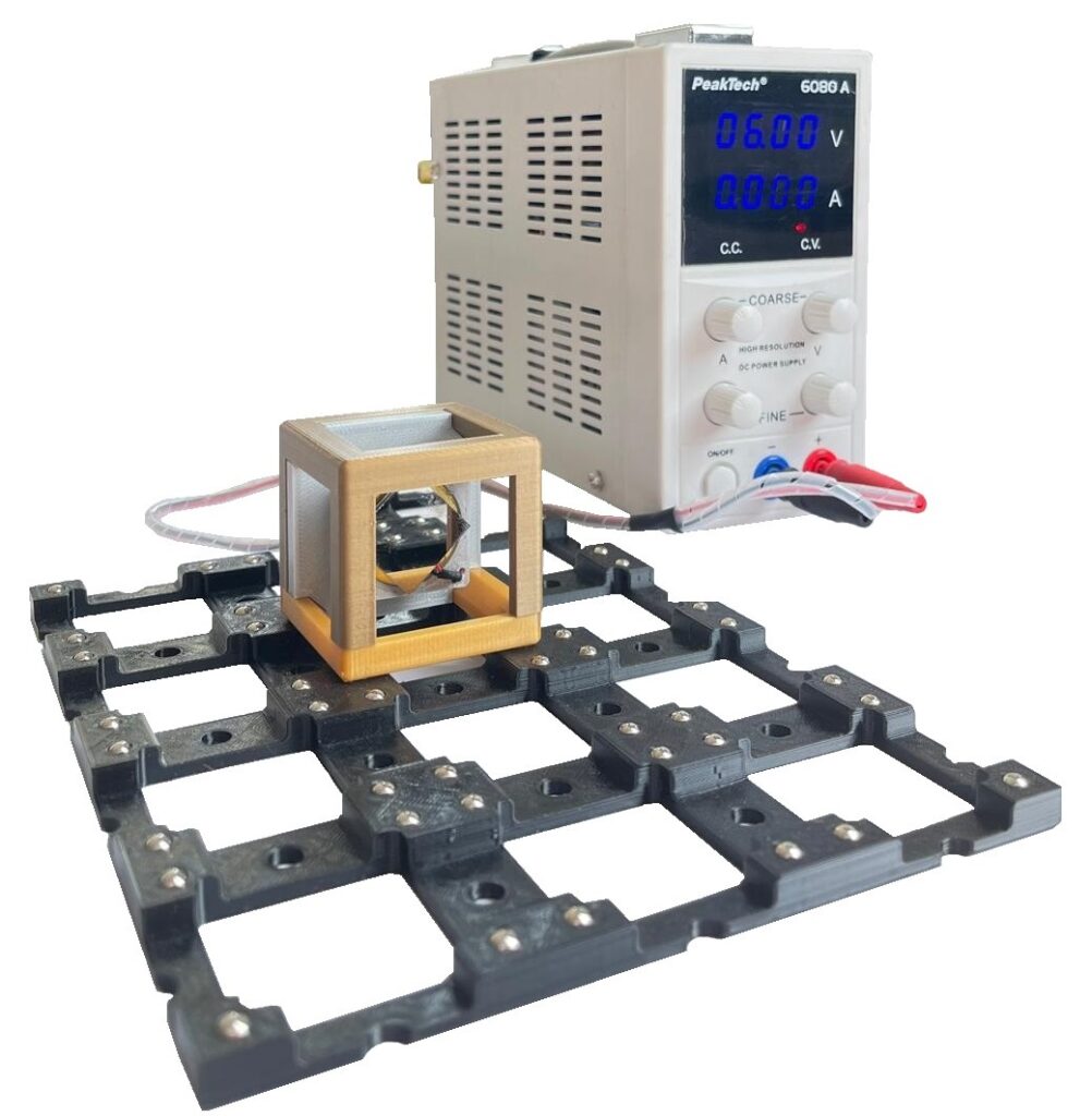
Below you will find information on assembly, special features and possible experiments.
Assembly
Exploded View

Material:
- 1x 01A_Go_V*_cube_base 1×1
- 1x 02A_Br_V*_cube_cover 1×1
- 1x 10A_Si_V*_insert 90°
- 1x 11D_Si_V*_mirror_plate_piezo
- 2x 03A_Re_V*_adjusting_screw_head
- 1x Adhesive pad (20 mm x 20 mm)
- 1x Piezoelectric element
- 1x Banana plug
- 1x Banana jack
- 3x Threaded insert, M3
- 1x Front surface mirror (22 mm x 22 mm)
- 4x Magnetic sphere, ø=5mm
- 5x Allen cylinder head screw, M3x12
- 2x Nut, self-locking, M3
- 2x Hexagon head screw, M3x40
- Heat-shrink tubing
- Twin stranded wire
- Superglue
- Soldering iron
Tools:
- Allen key – 2,5 mm
- Soldering iron (+ tip for threaded inserts)
- (Pipe-)wrench
- (ratchet + socket wrench attachment 12 mm)
- PCB holder for soldering
- Side cutter
- Stripping tool
- lighter
You will also find detailed instructions for assembly, as well as a component and material list with the STL files for 3D printing and links to the relevant stores.
Special Features
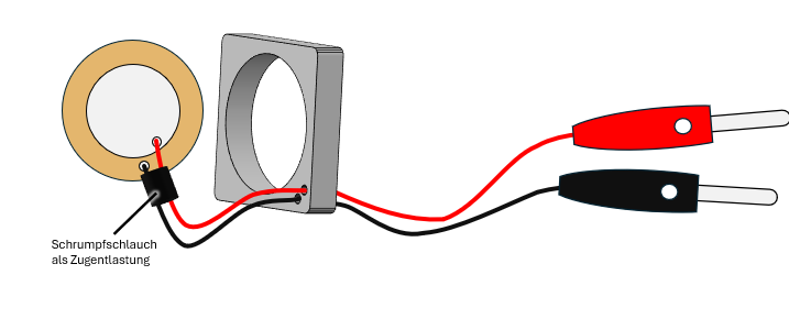
The soldering points on the piezo element are sensitive to mechanical stress. A piece of shrink tubing directly behind the soldering points can serve as strain relief.
Experiments
45° mirror
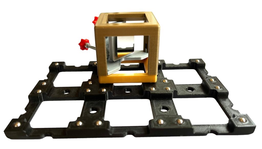
Below you will find information on assembly and possible experiments.
Assembly
Exploded View
Material:
- 1x 01A_Go_V*_cube_base 1×1
- 1x 02A_Br_V*_cube_cover 1×1
- 1x 10B_Si_V*_insert 45°
- 1x 11C_Si_V*_mirror_plate
- 2x 03A_Re_V*_adjusting_screw_head
- 1x Adhesive pad (20 mm x 20 mm)
- 1x Front surface mirror (22 mm x 22 mm)
- 4x Magnetic sphere, ø=5 mm
- 3x Threaded insert, M3
- 5x Allen cylinder head screw, M3x12
- 2x Nut, self-locking, M3
- 2x Hexagon head screw, M3x40
Tools:
- Allen key – 2,5 mm
- Soldering iron (+ tip for threaded inserts)
- (Pipe) pliers
- (ratchet + socket wrench attachment 12 mm)
- (tweezers)
You will also find detailed instructions for assembly, as well as a component and material list with the STL files for 3D printing and links to the relevant stores.
Experiments
- Mach-Zehnder interferometer – 2 pcs. / 3 pcs.
- Quantum eraser – 2 pcs. / 3 pcs.
- BB84 protocol / 1 pc.