
Interference patterns occur when coherent light waves overlap. The shape of these patterns depends on several factors, including the geometry of the beam path, the wavelengths of the light and the optical elements in the setup. Here you will find information on ring-shaped and hyperbolic interference patterns as well as an animation that illustrates how changes in certain parameters affect the interference pattern.
Ring-shaped interference patterns

The ring-shaped interference pattern shown is typical for interferometers with a small angular deviation between the interfering beams. It can be used to determine wavelengths, to measure optical path length changes and in high-precision measurement technology.
Development
Such patterns occur when two coherent beams of light meet at a small angle and overlap. The resulting interference rings are the result of constructive and destructive interference between these beams.
Possible causes
- If one of the mirrors is not exactly parallel to the second beam path, but is slightly tilted, for example, this leads to an angular dependence of the interference conditions, resulting in ring-shaped patterns.
- If a divergent or focused light source is used, spherical wavefronts can be created that are reflected along two slightly different paths and generate circular interference patterns.
- Subtle changes in the distance between the mirrors can change the pattern. This is a principle that is used, for example, in precision measurements or in optical coherence tomography.
Characteristics
- The light and dark rings correspond to areas of constructive and destructive interference respectively.
- The distance between the rings provides information about the wavelength of the light and the path length difference in the interferometer.
- A shift in the pattern can be caused by mechanical changes in the structure or by temperature changes, e.g. with the help of the piezo mirror module.
Hyperbolic interference patterns
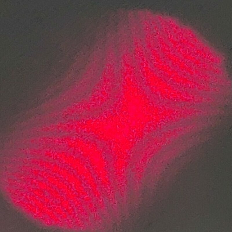
The hyperbolic interference pattern shown is typical of interferometers where there is a slight tilt of a mirror or a small angular difference between the interfering beams. Such patterns can be used to adjust interferometers, to analyze optical path length changes and to precisely measure surfaces or refractive index changes.
Development
Hyperbolic interference patterns occur when two largely parallel beams interfere with a small angular offset. This can occur in a Michelson interferometer or Mach-Zehnder interferometer if the mirrors or the beam splitter are not perfectly aligned.
Possible Causes
- If one of the mirrors in the interferometer is slightly tilted, the optical path of the reflected beams changes depending on the location on the detection plane.
- If the two light paths are of different lengths, the waves are superimposed with a phasic shift that is differently pronounced at different locations in the interference field.
- A light source that is not perfectly collimated (i.e. parallel) can cause different wavefront areas to meet at slightly varying angles, which influences the distortion of the interference pattern.
Characteristics
- The hyperbolic lines are locations with the same optical phase difference.
- Changes in the mirror angle or the optical path length shift the pattern.
- In holography and wave diagnostics, the analysis of such patterns helps to visualize surface profiles or air density fluctuations.
Animation
The animation shows how the interference pattern changes when certain parameters in the interferometer are varied.