

The LED cube serves as a light source for interference experiments. It is supplied with voltage via a cable so that the LED can be switched on and off. There are two versions of the power supply, which are explained in more detail here.
On this page you will find information about the assembly, the special features and the possible experiments.
Assembly
Exploded View
Material (Barrel connector):
- 1x 01A_Go_V*_cube_base 1×1
- 1x 02A_Br_V*_cube_cover 1×1
- 1x 10A_Si_V*_insert 90°
- 1x 11B_Si_V*_led_plate
- 2x 03A_Re_V*_adjusting_screw_head
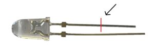
- 1x LED
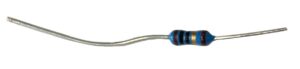
- 1x Resistor (10 Ohm)
- 1x Barrel connector
- 4x Threaded insert, M3
- 4x Magnetic sphere, ø=5mm
- 6x Allen cylinder head screw, M3x12
- 2x Nut, self-locking, M3
- 2x Hexagon head screw, M3x40
- Twin stranded wire (1 pc., ca. 25 cm)
- Spiral hose (1 pc., ca. 25 cm)
- Heat-shrink tubing
- Soldering tin
Tools:
- Allen key – 2,5 mm
- Soldering iron (+ tip for threaded inserts)
- (Pipe) pliers
- Side cutter
- PCB holder for soldering
- Lighter
- Stripping tool
- (Ratchet + socket wrench attachment 12 mm)
Circuit diagram

The circuit diagram shows the electrical connection between an LED and a barrel connector. The LED is shown on the left, which is connected to the barrel connector via two connections. A resistor (10 Ohm) is connected between the positive pole. The barrel connector serves as a connection for the battery box. The circuit makes it possible to supply the LED with power.
You will also find detailed instructions for assembly as well as a component and material list with the STL files for 3D printing and links to the relevant stores.
Special Features
When soldering the LED to the hollow plug, make sure that the wiring is assembled correctly and that the resistor is soldered to the positive pole of the LED. To do this, the positive pole of the LED and the resistor (10 Ohm) are shortened before soldering.
Experiments
- BB84 protocol – 1 pc.