
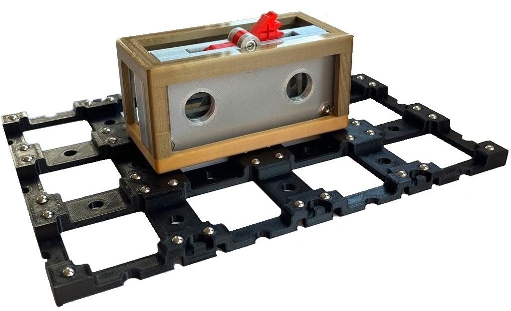
In the coupled polarizing filter module, two polarizing filters are held in a cube offset at 45° to each other and connected to each other with a switch so that they can be rotated in a coupled manner.
On this page you will find information about the assembly, the special features and the possible experiments.
Assembly
Exploded View
Material:
- 1x 01C_Go_V*_cube_base 1×2
- 1x 02C_Br_V*_cube_cover 1×2
- 1x 21A_Si_V*_coupled_polarizing_filter_frontplate
- 1x 21A_Si_V*_coupled_polarizing_filter_retaining_plate
- 1x 21A_Si_V*_coupled_polarizing_filter_intermediate_plate
- 1x 21A_Si_V*_coupled_polarizing_filter_gearwheel_left
- 1x 21A_Si_V*_coupled_polarizing_filter_gearwheel_right
- 2x 21A_Si_V*_coupled_polarizing_filter_grid_insert
- 1x 21A_Re_V*_coupled_polarizing_filter_switch
- 8x Allen cylinder head screw, M3x12
- 4x Nut, M3
- 2x Polarizing filter foil (17 mm x 17 mm)
Tools:
- Allen key – 2,5 mm
- Scissors / Knife
You will also find detailed instructions for assembly as well as a component and material list with the STL files for 3D printing and links to the relevant stores.
Special features
Alignment of the polarizing filter foil
The correct alignment of the polarizing filter is difficult when assembling. The Brewster angle can be used for this purpose:
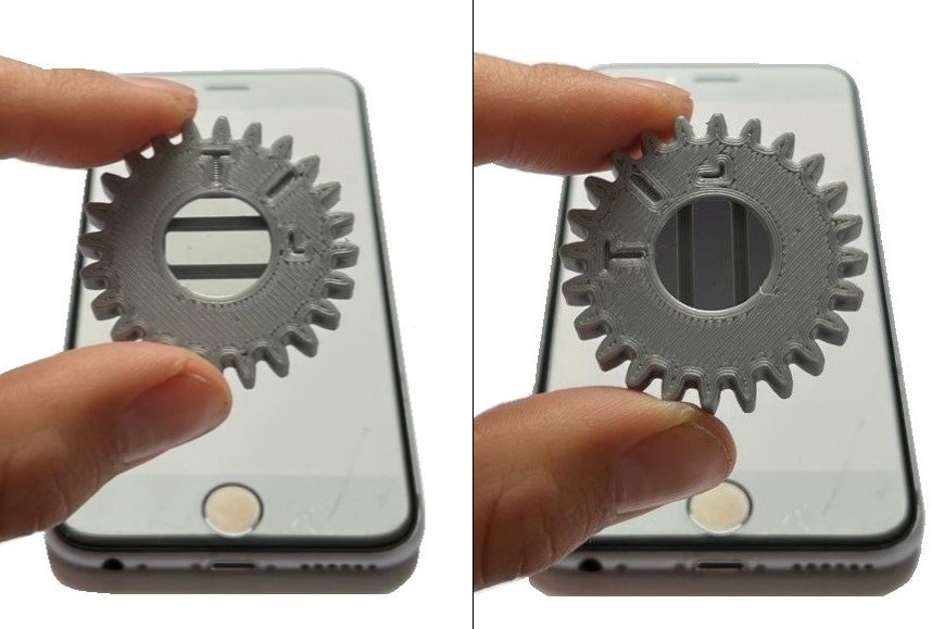
The orientation of the polarizing filter film can be determined using the Brewster angle, for example with a glass plate or the display of a smartphone. Hold the film in front of the reflected polarized light. The orientation of the polarizing film is 0° when the reflected light is absorbed. The alignment of the polarizing filter holder will help you: The alignment of the polarizing film is correct if the reflected light is transmitted when the struts in the holder are aligned horizontally and the light is absorbed when the struts are aligned vertically.
Filter cover
The filter cover is inserted into the corresponding opening after the polarizing filter and snaps into place to hold the polarizing filter firmly in place.
Intermediate plate
The intermediate plate is used to reduce the friction between the wheel and the retaining plate. As the underside of 3D-printed components usually has a comparatively smooth surface, the intermediate plate is aligned with this smooth side towards the wheel in order to further minimize friction. This effect can also be optimized by using graphite (e.g. from a pencil) as a lubricant.
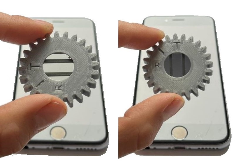
Rotary wheels and switches
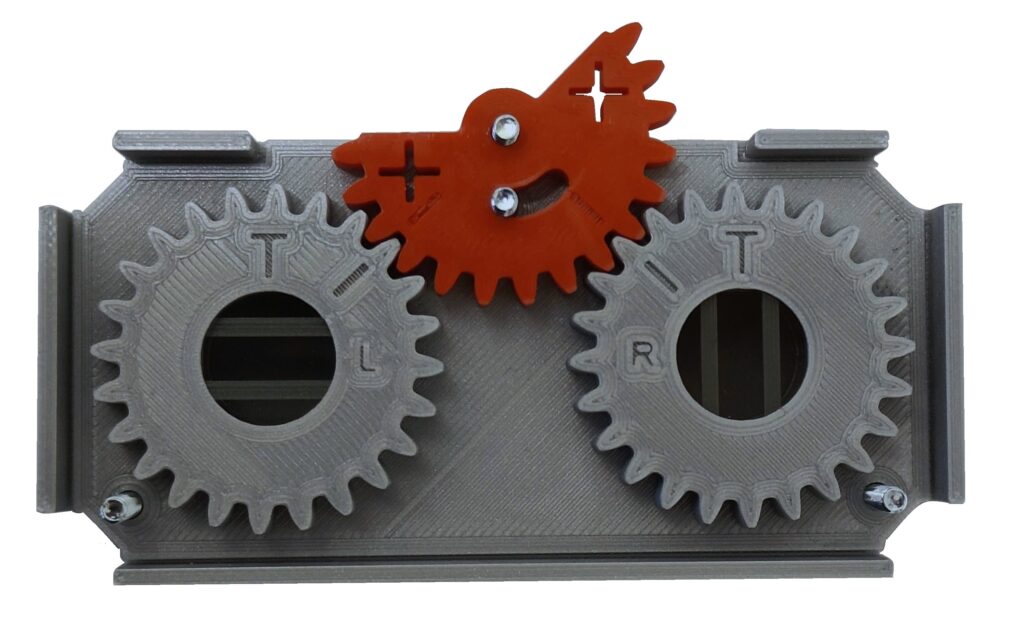 There is a left-hand (L) and a right-hand dial (R). When positioning on the bracket, make sure that the left-hand dial is positioned on the left and the right-hand dial on the right so that the letters L and R are legible. In addition, when the wheels are positioned correctly, the upper line of the T is exactly horizontal.
There are two lines on the switch. The switch must be positioned during assembly so that the lines are in line with those on the rotary wheels.
Experiments
- BB84-Protocol – 1 pc.